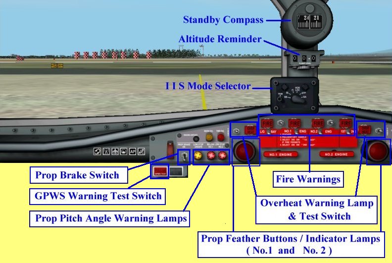
Overheat Warning Lamp & Test Switch: Self-explanatory

Prop Feather Buttons / Indicator Lamps:
Push button (by mouth click) to activate the feathering of propellers. (pitch angle becomes 90 degree
in order to reduce drag) Lamp is lit when activated.

Prop Pitch Angle Warning Light:
These lamp will be lit to indicate that prop pitch angles are inadequate for flying. The lamp on the
left side is lit when either one of prop pitch are inadequate, the middle lamp is lit when pitch angle
for No1 engine and the lamp on the right side is lit for No2 engine.

Propeller Brake Switch:
Switch on (by mouth click) to shut down both engines. Additionally, No1 engine prop spinning will be
braked.

GPWS Warning Light and Test Switch:
Pressing down (by mouth) the GPWS Warning Lamp will TEST the system.
> I I S Mode Selector:
Click HERE for explanation of I I S !
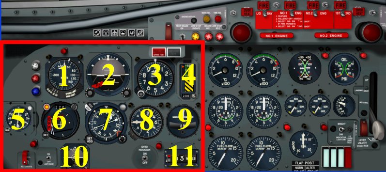
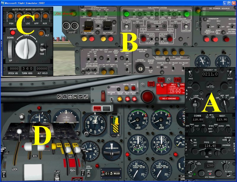
Left hand side of Main Panel.
1.	Air Speed Indicator :
         Speed bug setting by mouth click at the bottom of instrument.
         Click on left side for  +  and  right side for  -
2.	HZ-4 Horizon Flight Director :
         HSI integrated with FD by IIS. FD flag appears at the left bottom corner, when FD fails,
         or when IIS is on SB mode. G flag appears at right bottom corner, when artificial horizon
         is unserviceable.
3.	Altimeter :
         Field elevation bug setting is possible by mouth click on the bug set knob at the left
         bottom corner. Due to space constrain on the Altimeter, thre is no readable QNH value in
         the Altimeter. To automatically calibrate barometric pressure to the correct value, press
         the B key.
4.	Radio Altimeter :
         Upper limit 2500 feet. Lamp on the top will be lit when DH is reached. DH can be set by
         mouth click in the small window at bottom. Warning Flag appears when RA fails, or test
         knob at the right bottom end is pressed.
5.	Clock :
         Stop watch knob at the right top end, and the time setting knob at the left bottom end.
6.	R-1 Indicator (Pictorial Deviation Indicator) : Click HERE for explanation!.
7.	C-6A Indicator :
         The heading is indicated by the gyroscopically controlled compass. VOR and ADF needle
         are integrated and Course setting is done by mouth click on SET HDG knob at the left
         bottom corner. OFF warning flag appears at the right end corner when power is lost.
8.	Rate of Climb Indicator :
         Measures rate of climb or descent in hundreds of feet per minute.
9.	Turn and Slip Indicator :
         The needle indicates the direction and rate of your turn. A larger deflection indicates
         a higher turn rate. The ball in the inclinometer at the bottom indicaes both slip and
         skid attitude.
10.	Standby Horizon Indicator :
         Self-explanatory. ON and OFF are switchable by mouth click on the switch available
         beside the DME system.
11.	DME System :
         NAV1 and NAV2 are switchable by mouth click on the left side of instrument.
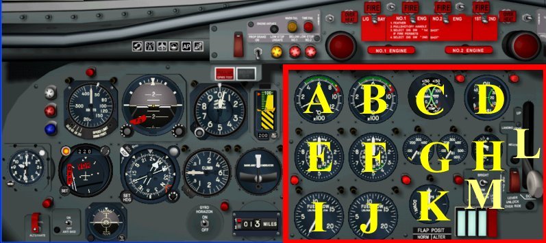
Right hand side of Main Panel. (Engine gauges)
A:	Turbine Exhaust Temperature Gauge for No.1 Engine.
B:	Turbine Exhaust Temperature Gauge for No.2 Engine.
C:	Oil Temperature Gauge.
D:	Oil Pressure Gauge.
E:	Tachometer for Engine No.1 Engine.
F:	Tachometer for Engine No.2 Engine.
G:	Torque Pressure gauges. (left and right engine)
H:	Outside Air Temperature Gauge.
I:	Fuel Flow Gauge for No.1 Engine.
J:	Fuel Flow Gauge for No.2 Engine.
K:	Flap Position Indicator. (use the key F5 F6 F7 F8)
L:	Landing Gear Lever.
M:	Gear Lamp Test Switch and 3 gear lock/unclock lamps.
         3 lamps from the left to right: Left main gear, Nose gear and Right main gear.
         Light blue lamps will be lit during the gears transition, and when gears are locked.
         The Red Warning lamp at the right end will be lit during the gear transition, and
         also when Gears are downed but unlocked.